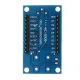
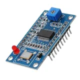
SKU: OT3459 Numer artykułu: NA416 EAN: 8720618690838

Generatory sygnału / generatory funkcyjne są bardzo przydatne od RF po logikę embedded, ale zwykle nie są super tanie.
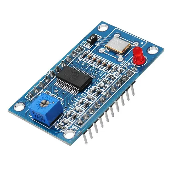
Dobra wiadomość: dzięki temu modułowi AD9850 DDS, przy odrobinie montażu, zbudujesz własny, elastyczny, funkcjonalny i łatwy w obsłudze generator częstotliwości Arduino!
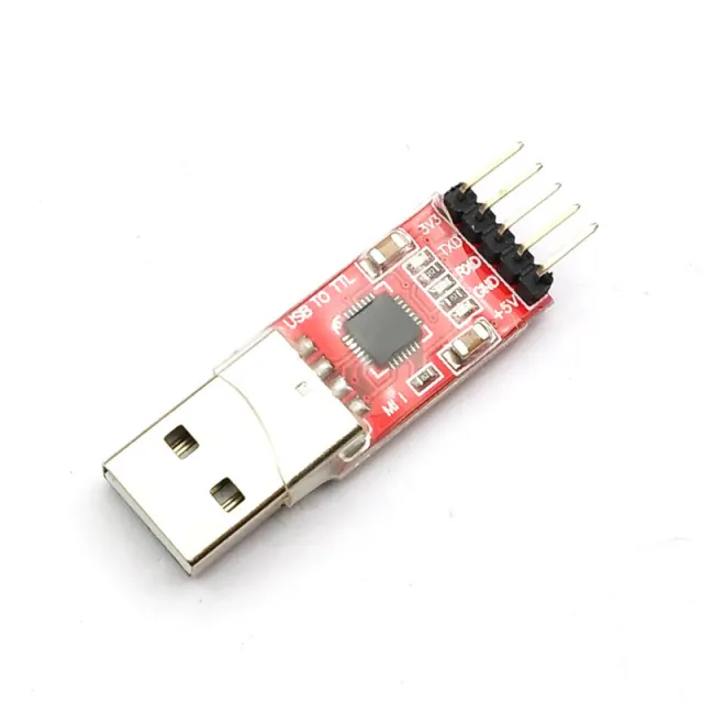
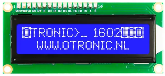
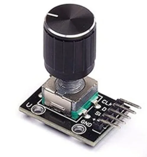
Z wyświetlaczem LED, potencjometrem obrotowym i Arduino stworzysz łatwy w użyciu, wolnostojący generator sygnału. (Nie zapomnij wtedy o zakupie konwertera CP2102 USB na TTL Serial, jeśli jeszcze go nie masz)
Możesz też zdecydować się na połączenie go wyłącznie z Arduino Uno na płytce stykowej.
Zupełnie inną drogą jest użycie tego modułu do stworzenia własnego Software Defined Radio (SDR).
Krótko mówiąc, świetny moduł do rozpoczęcia pracy!
Cechy:
ZASTOSOWANIA:
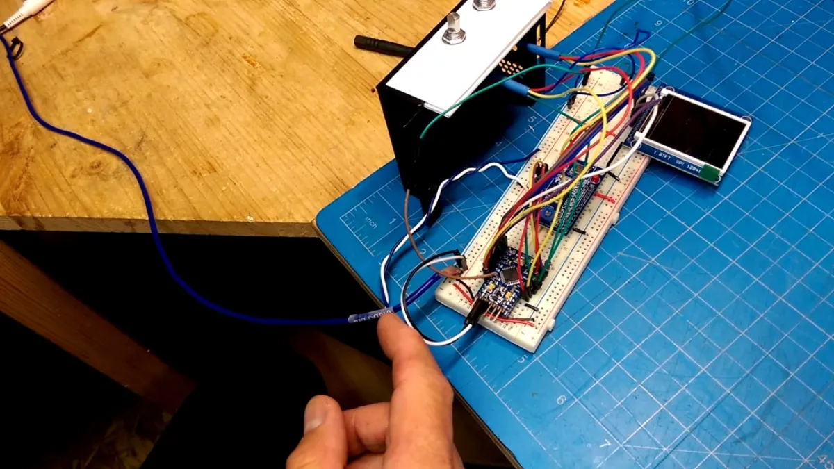
Odtworzenie spowoduje załadowanie filmu z YouTube.
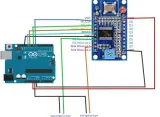
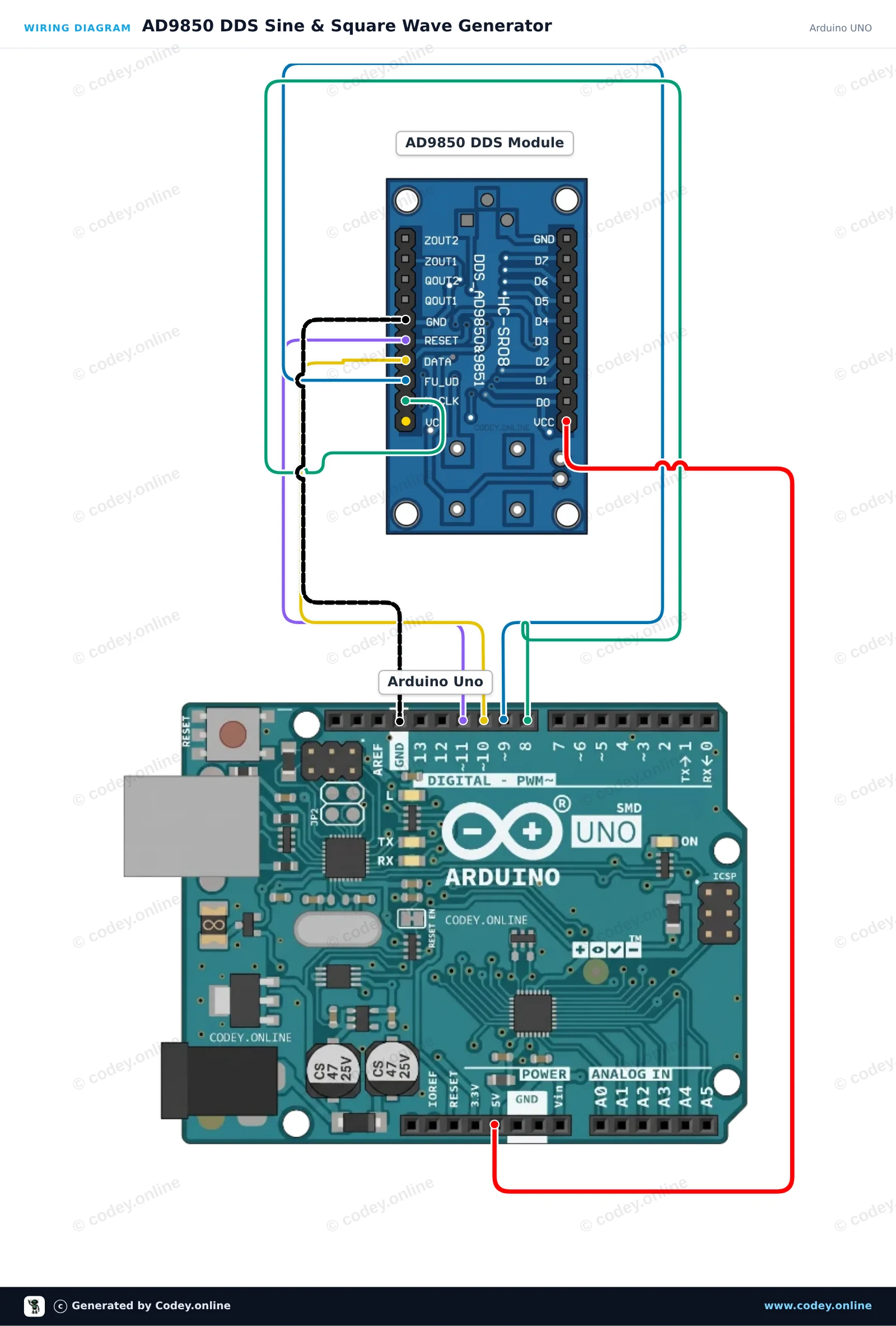
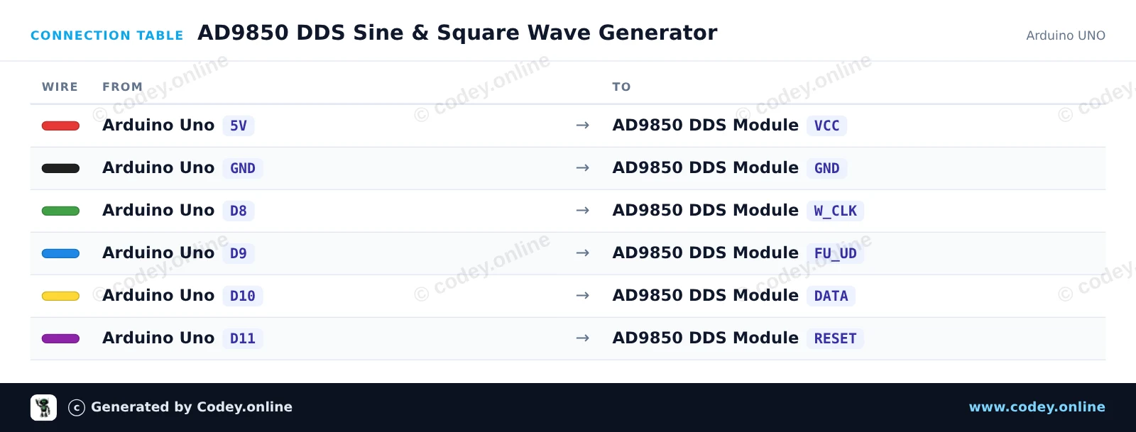
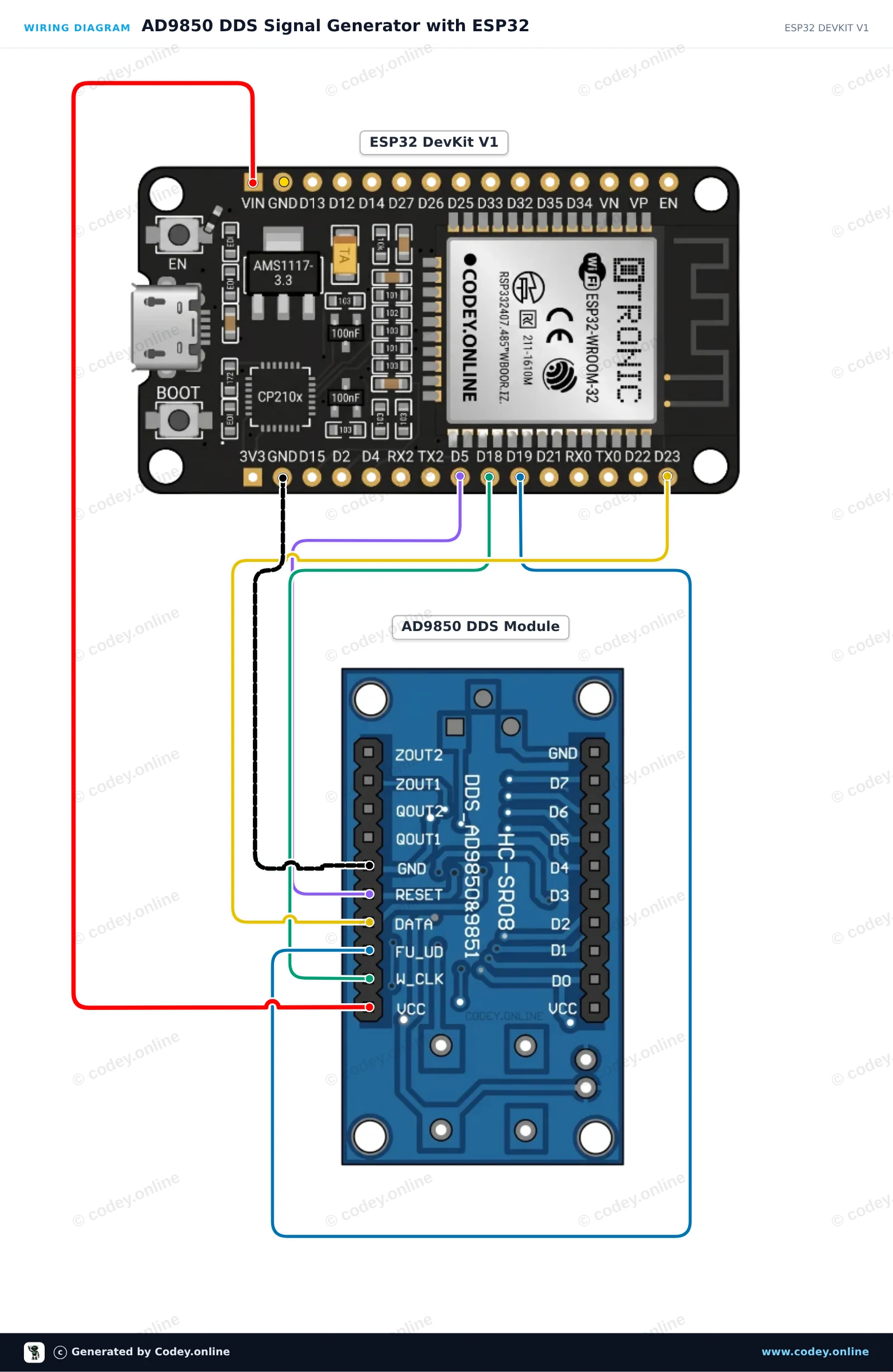
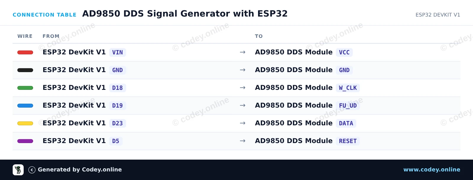
Tak podłączysz AD9850 DDS Generator sygnału Module do Arduino UNO lub ESP32, z przykładowym szkicem, który możesz od razu wgrać.
Ten projekt steruje modułem AD9850 DDS przez 4-przewodowy interfejs szeregowy, aby generować precyzyjne częstotliwości fali sinusoidalnej i prostokątnej. Arduino inicjalizuje moduł DDS i okresowo przełącza częstotliwość wyjściową między 1 kHz, 10 kHz i 100 kHz. Podłącz oscyloskop lub licznik częstotliwości do ZOUT1 (fala sinusoidalna) lub QOUT1 (fala prostokątna), aby sprawdzić sygnał wyjściowy.
/*
 * ==================================================================
 *  Generated by Codey.online  —  https://www.codey.online
 * ==================================================================
 *  Project   : AD9850 DDS Sine & Square Wave Generator
 *  Board     : Arduino UNO (arduino:avr:uno)
 *  Parts     : AD9850 DDS Signal Generator Module
 *  Libraries : none (built-in)
 *
 *  Codey Online is an AI-powered browser IDE for Arduino and ESP32.
 *  Describe your project and Codey writes the code, draws the wiring
 *  diagram and uploads it to your board, straight from the browser.
 *  This code is free to use, modify and share, without warranty.
 * ==================================================================
 */

const int PIN_W_CLK = 8;
const int PIN_FQ_UD = 9;   // Labeled FU_UD on module
const int PIN_DATA  = 10;
const int PIN_RESET = 11;

const unsigned long AD9850_REF_CLOCK = 125000000UL; // 125 MHz reference oscillator

void pulsePin(int pin) {
  digitalWrite(pin, HIGH);
  delayMicroseconds(1);
  digitalWrite(pin, LOW);
  delayMicroseconds(1);
}

void ad9850Reset() {
  digitalWrite(PIN_RESET, HIGH);
  delayMicroseconds(1);
  digitalWrite(PIN_RESET, LOW);
  delayMicroseconds(1);
  pulsePin(PIN_W_CLK);
  pulsePin(PIN_FQ_UD);
}

void ad9850SetFrequency(double freqHz) {
  // Calculate 32-bit tuning word: (freq * 2^32) / ReferenceClock
  uint32_t tuningWord = (uint32_t)((freqHz * 4294967296.0) / (double)AD9850_REF_CLOCK);

  // Transmit 32-bit frequency tuning word (LSB first)
  for (int i = 0; i < 32; i++) {
    digitalWrite(PIN_DATA, (tuningWord >> i) & 0x01);
    pulsePin(PIN_W_CLK);
  }

  // Transmit 8 control/phase bits (all 0 for normal operation)
  for (int i = 0; i < 8; i++) {
    digitalWrite(PIN_DATA, LOW);
    pulsePin(PIN_W_CLK);
  }

  // Latch the updated frequency into the DDS core
  pulsePin(PIN_FQ_UD);
}

void setup() {
  pinMode(PIN_W_CLK, OUTPUT);
  pinMode(PIN_FQ_UD, OUTPUT);
  pinMode(PIN_DATA, OUTPUT);
  pinMode(PIN_RESET, OUTPUT);

  digitalWrite(PIN_W_CLK, LOW);
  digitalWrite(PIN_FQ_UD, LOW);
  digitalWrite(PIN_DATA, LOW);
  digitalWrite(PIN_RESET, LOW);

  Serial.begin(115200);
  while (!Serial) {
    ;
  }

  Serial.println(F("AD9850 DDS Generator Initialized"));
  ad9850Reset();
}

void loop() {
  const double testFrequencies[] = {1000.0, 10000.0, 100000.0};

  for (int i = 0; i < 3; i++) {
    double freq = testFrequencies[i];
    ad9850SetFrequency(freq);
    Serial.print(F("Output frequency set to: "));
    Serial.print(freq);
    Serial.println(F(" Hz"));
    delay(3000);
  }
}Wiring diagram and example code generated by Codey.online — https://www.codey.online
Ten projekt generuje precyzyjne sygnały sinusoidalne i prostokątne za pomocą modułu DDS AD9850 sterowanego przez ESP32. Sketch przechodzi przez sekwencję częstotliwości (1 kHz, 10 kHz, 100 kHz i 1 MHz) co 3 seconds. Podłącz oscyloskop lub licznik częstotliwości do ZOUT1 dla wyjścia sinusoidalnego lub do QOUT1 dla wyjścia prostokątnego.
/*
 * ==================================================================
 *  Generated by Codey.online  —  https://www.codey.online
 * ==================================================================
 *  Project   : AD9850 DDS Signal Generator with ESP32
 *  Board     : ESP32 DEVKIT V1 (esp32:esp32:esp32doit-devkit-v1)
 *  Parts     : AD9850 DDS Signal Generator Module
 *  Libraries : none (built-in)
 *
 *  Codey Online is an AI-powered browser IDE for Arduino and ESP32.
 *  Describe your project and Codey writes the code, draws the wiring
 *  diagram and uploads it to your board, straight from the browser.
 *  This code is free to use, modify and share, without warranty.
 * ==================================================================
 */

// AD9850 DDS Signal Generator Demo on ESP32
const int W_CLK_PIN = 18;
const int FU_UD_PIN = 19;
const int DATA_PIN  = 23;
const int RESET_PIN = 5;

// 125 MHz reference clock crystal on board
const double REF_CLK = 125000000.0;

const double testFrequencies[] = {1000.0, 10000.0, 100000.0, 1000000.0};
const int numFrequencies = sizeof(testFrequencies) / sizeof(testFrequencies[0]);
int currentFreqIndex = 0;

void pulseHigh(int pin) {
  digitalWrite(pin, HIGH);
  delayMicroseconds(1);
  digitalWrite(pin, LOW);
  delayMicroseconds(1);
}

void resetAD9850() {
  pulseHigh(RESET_PIN);
  pulseHigh(W_CLK_PIN);
  pulseHigh(FU_UD_PIN); // Enable serial load mode
}

void sendFrequency(double frequency) {
  uint32_t tuningWord = (uint32_t)((frequency * 4294967296.0) / REF_CLK);

  // Send 32-bit frequency tuning word (LSB first)
  for (int i = 0; i < 32; i++) {
    digitalWrite(DATA_PIN, (tuningWord >> i) & 0x01);
    pulseHigh(W_CLK_PIN);
  }

  // Send 8 control/phase bits (0x00 for 0 phase offset)
  for (int i = 0; i < 8; i++) {
    digitalWrite(DATA_PIN, LOW);
    pulseHigh(W_CLK_PIN);
  }

  // Latch new frequency to output
  pulseHigh(FU_UD_PIN);
}

void setup() {
  Serial.begin(115200);
  delay(500);
  Serial.println("AD9850 DDS Signal Generator Initializing...");

  pinMode(W_CLK_PIN, OUTPUT);
  pinMode(FU_UD_PIN, OUTPUT);
  pinMode(DATA_PIN,  OUTPUT);
  pinMode(RESET_PIN, OUTPUT);

  digitalWrite(W_CLK_PIN, LOW);
  digitalWrite(FU_UD_PIN, LOW);
  digitalWrite(DATA_PIN,  LOW);
  digitalWrite(RESET_PIN, LOW);

  resetAD9850();
  Serial.println("AD9850 ready!");
}

void loop() {
  double freq = testFrequencies[currentFreqIndex];
  sendFrequency(freq);

  Serial.print("Output frequency set to: ");
  Serial.print(freq, 0);
  Serial.println(" Hz");

  currentFreqIndex = (currentFreqIndex + 1) % numFrequencies;
  delay(3000);
}Wiring diagram and example code generated by Codey.online — https://www.codey.online





 English
  Nederlands
  Frans
Frans  Deutsch
  Italiano
  Español
  Suomi
Suomi  Dansk
Dansk  Ελληνικά
  Български
  Čeština
  Hrvatski
  Aileen