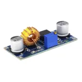
SKU: OT2004-A113 Numer artykułu: AA270 EAN: 8179262862427

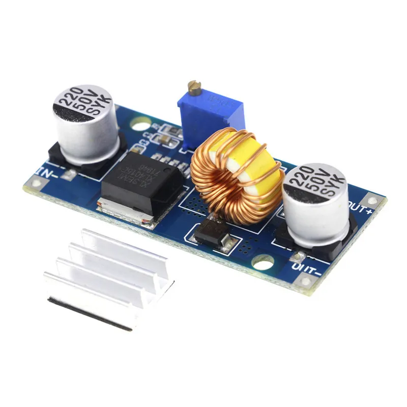
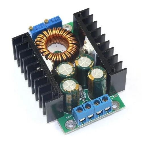
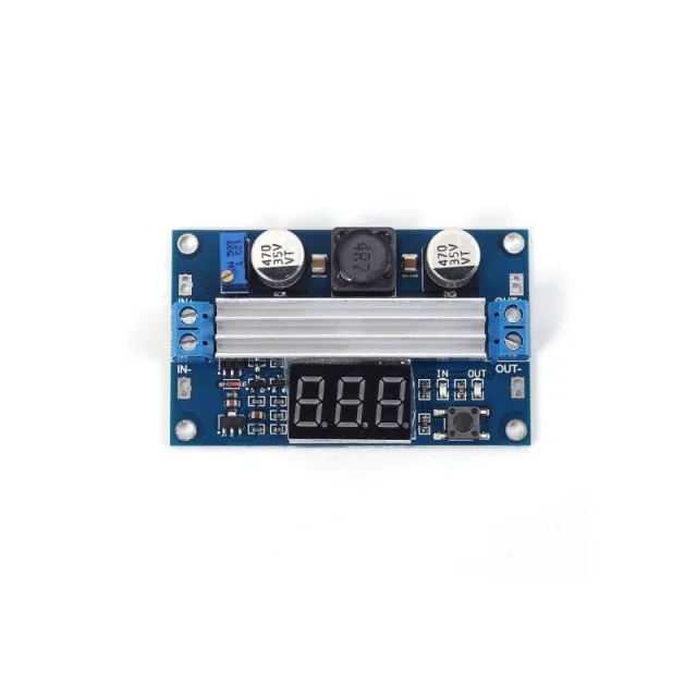
Napięcie wejściowe 4-38VDC
Napięcie wyjściowe 1.25-36VDC, regulowane
Moc wyjściowa 0-5A, z zabezpieczeniem przeciwzwarciowym wyjścia.
Maksymalne wyjście 75W z zabezpieczeniem termicznym
W zestawie radiator, dostarczany osobno do samodzielnego montażu. Można go zamocować za pomocą dołączonej taśmy 3M.
Afmetingen
Lengte: 5,4cm
Breedte: 2,45cm
Hoogte: 1,7cm
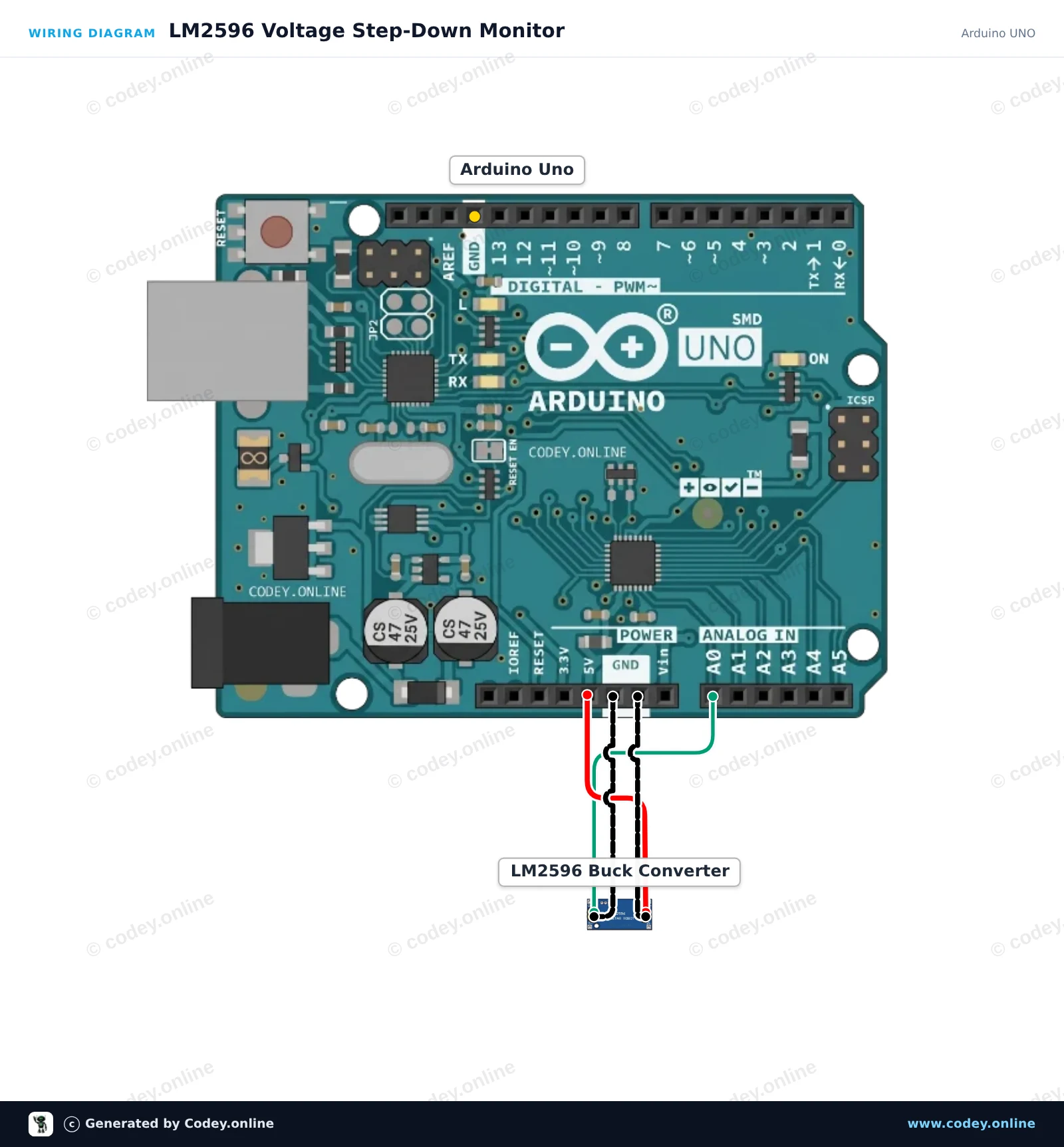
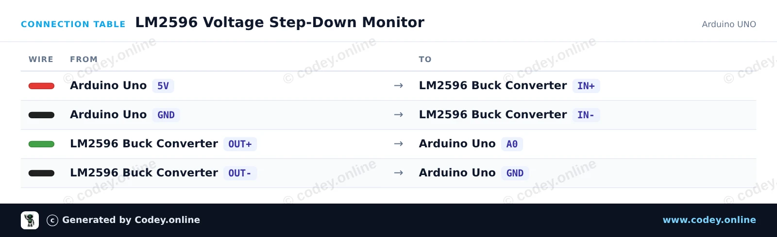
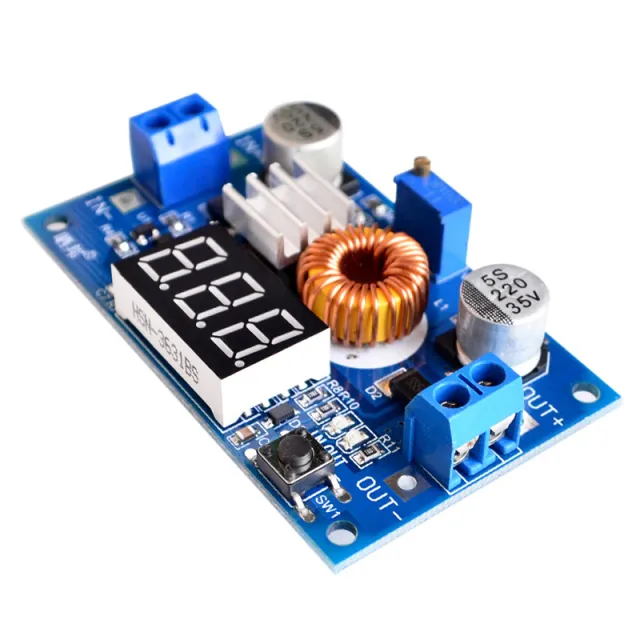
Tak podłączysz Regulowany moduł step-down 4~38V 5A 96% wysoka wydajność XL4015 do Arduino UNO lub ESP32, z przykładowym szkicem, który możesz od razu wgrać.
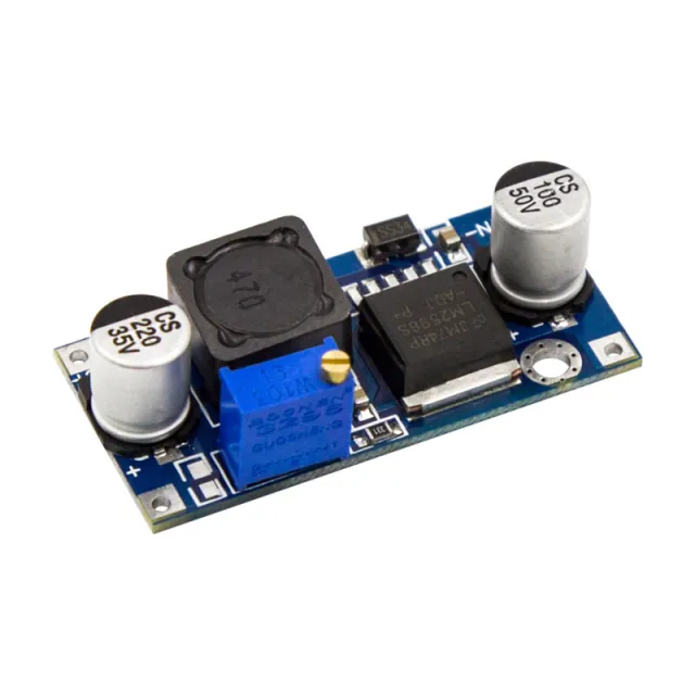
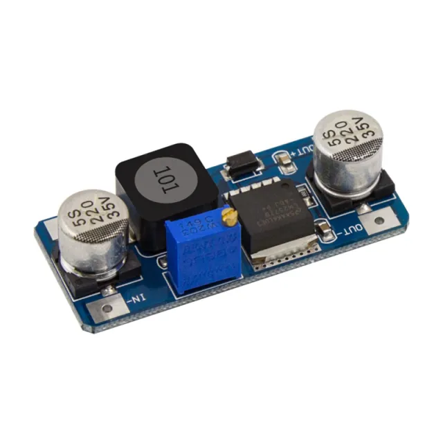
Ten projekt zasila moduł step-down LM2596 z linii 5V Arduino i mierzy jego regulowane napięcie wyjściowe na pinie analogowym A0. Wyreguluj wbudowany potencjometr małym śrubokrętem, aby obserwować zmiany napięcia w czasie rzeczywistym wyświetlane w Serial Monitor (utrzymuj wyjście poniżej 5V).
/*
 * ==================================================================
 *  Generated by Codey.online  —  https://www.codey.online
 * ==================================================================
 *  Project   : LM2596 Voltage Step-Down Monitor
 *  Board     : Arduino UNO (arduino:avr:uno)
 *  Parts     : Adjustable Step-down Module 3-40VDC 1.5-35VDC LM2596
 *  Libraries : none (built-in)
 *
 *  Codey Online is an AI-powered browser IDE for Arduino and ESP32.
 *  Describe your project and Codey writes the code, draws the wiring
 *  diagram and uploads it to your board, straight from the browser.
 *  This code is free to use, modify and share, without warranty.
 * ==================================================================
 */

const int voltagePin = A0;

void setup() {
  Serial.begin(115200);
  while (!Serial) {
    ; // Wait for serial port to connect
  }
  Serial.println(F("LM2596 Step-Down Voltage Monitor"));
  Serial.println(F("Turn the onboard trimmer to adjust the output voltage (0-5V)."));
}

void loop() {
  int rawValue = analogRead(voltagePin);
  float voltage = rawValue * (5.0 / 1023.0);

  Serial.print(F("ADC Value: "));
  Serial.print(rawValue);
  Serial.print(F(" | Output Voltage: "));
  Serial.print(voltage, 2);
  Serial.println(F(" V"));

  delay(500);
}Wiring diagram and example code generated by Codey.online — https://www.codey.online
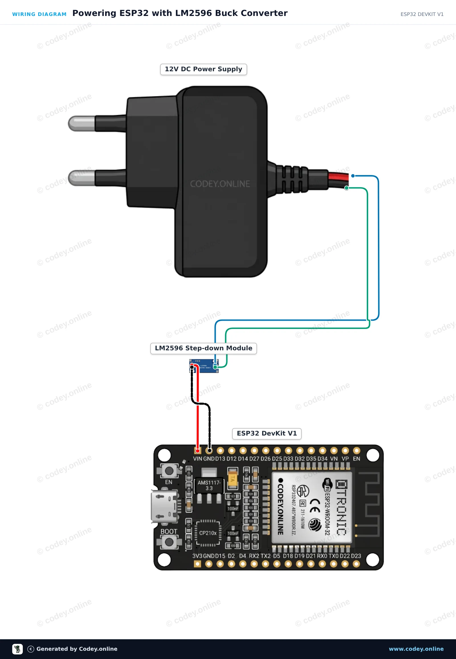
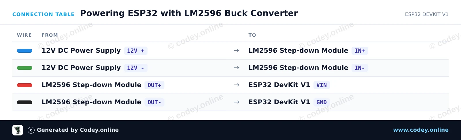
Przed podłączeniem ESP32 użyj multimetru, aby wyregulować potencjometr trimmera LM2596, aż OUT+ pokaże dokładnie 5.0V. Moduł wydajnie obniża wejściowe 12V do stabilnego wyjścia 5V, aby zasilać ESP32 przez VIN i GND. Po podłączeniu ESP32 uruchamia się, miga wbudowaną diodą statusu i wysyła komunikaty heartbeat przez Serial.
/*
 * ==================================================================
 *  Generated by Codey.online  —  https://www.codey.online
 * ==================================================================
 *  Project   : Powering ESP32 with LM2596 Buck Converter
 *  Board     : ESP32 DEVKIT V1 (esp32:esp32:esp32doit-devkit-v1)
 *  Parts     : Adjustable Step-down Module 3-40VDC 1.5-35VDC LM2596
 *  Libraries : none (built-in)
 *
 *  Codey Online is an AI-powered browser IDE for Arduino and ESP32.
 *  Describe your project and Codey writes the code, draws the wiring
 *  diagram and uploads it to your board, straight from the browser.
 *  This code is free to use, modify and share, without warranty.
 * ==================================================================
 */

// LM2596 Step-Down Buck Converter ESP32 Power Demo
// Note: Always adjust LM2596 output to 5V before connecting to VIN!

const int LED_PIN = 2; // Onboard LED

void setup() {
  Serial.begin(115200);
  pinMode(LED_PIN, OUTPUT);

  Serial.println("LM2596 Step-Down Buck Converter Demo");
  Serial.println("ESP32 successfully running on regulated 5V power!");
}

void loop() {
  // Turn LED on
  digitalWrite(LED_PIN, HIGH);
  Serial.print("Uptime: ");
  Serial.print(millis() / 1000);
  Serial.println(" s | Power Status: OK (LED ON)");
  delay(500);

  // Turn LED off
  digitalWrite(LED_PIN, LOW);
  delay(500);
}Wiring diagram and example code generated by Codey.online — https://www.codey.online






 English
  Nederlands
  Frans
Frans  Deutsch
  Italiano
  Español
  Suomi
Suomi  Dansk
Dansk  Ελληνικά
  Български
  Čeština
  Hrvatski
  Aileen